
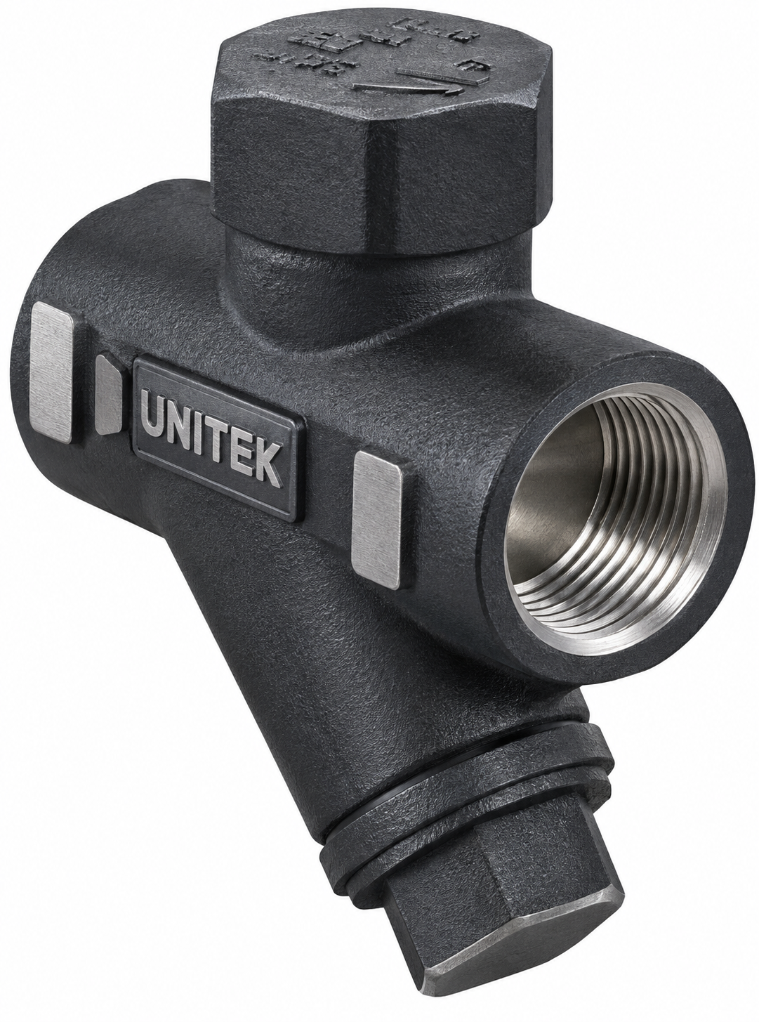
THERMODYNAMIC STEAM TRAP
Product Description
| Body : | ASTM A 351 Gr CF8 | CA15 |
| Trims : | 13 Cr | 18 Cr 8 Ni |
| Max Inlet Pressure : | 32 Kg/Cm ² AT 425 °C |
| Minimum Pressure : | 0.25 Kg/Cm ² |
| Ends : | Screwed to BSP |
| HYD Test Pressure : | 911 Psig (64 Kg/Cm ²) |
| Size Range : | 15 MM TO 25 MM |
Description
Thermodynamic Steam Trap Manufacturer in India
A Thermodynamic Steam Trap is an essential automatic condensate-removal device engineered to discharge condensed water from industrial steam systems while retaining live steam under suitable operating conditions. In modern steam distribution networks, boiler systems, and power generation plants, the continuous generation of condensate is an unavoidable thermodynamic byproduct of heat transfer. Efficient condensate removal helps prevent water logging, protects thermal equipment, and maintains high heat transfer efficiency across process heating equipment and steam lines.
Unitek Valves operates as a trusted manufacturer, supplier, and exporter of industrial valves and steam-system products in Mumbai, India, providing reliable condensate-management solutions for domestic industrial plants and international export markets.
What is a Thermodynamic Steam Trap?
A Thermodynamic Steam Trap is a specialized self-contained automatic valve designed to differentiate between steam and condensate based on their thermodynamic properties.
-
Condensate Removal: Its primary purpose is to remove liquid water as soon as it forms in the piping circuit without allowing live steam to escape.
-
Automatic Operation: Operating entirely on the dynamic effects of the working fluid, the trap requires no external power source or manual adjustment.
-
Disc-Based Design: The core operating mechanism relies on a movable disc that responds dynamically to changes in fluid velocity, pressure, and temperature.
Unlike mechanical traps that use floats or thermostatic traps that rely on temperature expansion elements, a thermodynamic trap utilizes a cyclical disc mechanism suited for high-pressure and high-temperature steam utility applications.
How Does a Thermodynamic Steam Trap Work?
The operational cycle of a Thermodynamic Steam Trap relies on the distinct physical behaviors of liquid condensate and flash steam passing through the valve body:
-
Condensate Entry: Condensate entering the trap flows into the inlet passage and exerts pressure against the underside of the disc, lifting it from the seat.
-
Condensate Discharge: With the disc lifted, accumulated condensate flows freely across the seat and out through the discharge passage into the return line.
-
Flash Steam Formation: As hot condensate approaches steam saturation temperature, a portion of the liquid flashes into steam (flash steam) as the pressure drops across the valve.
-
Velocity and Pressure Effects: The high-velocity mixture of flash steam and condensate flowing under the disc creates a low-pressure area (Bernoulli effect), while flash steam velocity increases.
-
Disc Movement Toward the Seat: The high-velocity flow creates a localized pressure drop beneath the disc, while pressure builds up in the control chamber above the disc.
-
Closing Cycle: The higher pressure in the control chamber snaps the disc down firmly onto the seat, sealing the valve against the escape of live steam.
-
Reopening Cycle: As heat radiates from the top control chamber, the trapped steam condenses, lowering the pressure above the disc. When new incoming condensate arrives and exerts sufficient pressure from below, the disc lifts again, and the cycle repeats.
Disc Type Thermodynamic Steam Trap Design
A Disc Type Thermodynamic Steam Trap features a robust, streamlined construction designed for durability under demanding thermal cycles. General construction elements include:
-
Body: Houses the inlet and outlet flow paths and provides structural containment.
-
Cover (Cap): Encloses the top control chamber above the disc.
-
Disc: The sole moving part, acting as the primary closing element.
-
Seat: The precision-machined ring against which the disc seals.
-
Control Chamber: The volume above the disc that governs the snap-action closing mechanism.
-
Inlet and Outlet Passages: Direct fluid flow into and out of the internal operating zone.
Actual dimensions, material selection, and internal configurations depend strictly on the specific product design and manufacturing specifications.
Thermodynamic Steam Trap with Inbuilt Strainer
In many industrial piping installations, pipeline debris such as welding scale, rust, or pipe sealant can travel through steam lines and interfere with valve seating surfaces.
-
Strainer Purpose: Where incorporated into the product design, a Thermodynamic Steam Trap with Inbuilt Strainer features an integrated filtration screen that captures particulate matter before it reaches the disc and seat.
-
Design Specificity: An inbuilt strainer is a product-specific feature and is not present in every thermodynamic steam trap model. Selection depends on piping cleanliness, maintenance practices, and specific installation requirements.
Thermodynamic Steam Trap for Boiler Systems
Boiler installations and associated steam generation loops handle high-energy steam environments. A Thermodynamic Steam Trap for Boiler Systems is frequently installed on main steam headers, superheater drain points, and high-pressure distribution lines to ensure prompt condensate removal. Effective condensate drainage protects boiler auxiliary systems and supports reliable steam delivery across the facility.
Thermodynamic Steam Trap for Steam Pipelines
Steam distribution pipelines stretch across extensive industrial plants, where thermal radiation through pipe walls inevitably generates condensate. Installing a Thermodynamic Steam Trap for Steam Lines at strategic drain points along the pipeline helps keep distribution headers clear of accumulated liquid. Proper condensate removal supports stable steam-system operation and helps maintain dry steam supply at point-of-use equipment.
Thermodynamic Steam Trap for Power Plants
Thermal power plants and co-generation facilities handle massive steam volumes operating at elevated pressures and temperatures. A Thermodynamic Steam Trap for Power Generation plays an important role in managing condensate across turbine extraction lines, high-pressure utility headers, and power plant steam networks, ensuring that moisture is effectively removed from high-energy circuits.
Thermodynamic Steam Trap for Industrial Piping & Process Steam
Industrial manufacturing relies heavily on clean, reliable process steam for heating, evaporation, jacketed vessels, and heat exchangers. Suitable applications are found across industries such as:
-
Chemical processing plants
-
Petrochemical units
-
Oil & Gas facilities
-
Power generation stations
-
Manufacturing and textile units
-
Industrial steam utility networks
Suitability depends strictly on actual operating conditions, pressure differentials, and specific application requirements.
Materials & Construction
A robust structural design ensures that the body shell and internal disc components withstand demanding thermal cycling and pressure forces. Potentially applicable materials include:
-
Carbon Steel: Widely specified for general industrial steam distribution lines and utility networks.
-
Cast Steel: Utilized in robust industrial applications requiring high mechanical strength.
-
Stainless Steel: Selected for corrosion resistance, longevity, and resistance to environmental scaling in steam service.
Actual material selection depends strictly on steam conditions, operating pressure, temperature, corrosion conditions, specific application, and project specifications.
Flanged and Screwed Thermodynamic Steam Traps
Connection arrangements must match the piping specifications of the installation site:
-
Flanged Connections: Provided where bolted flange joints are required for heavy-duty industrial piping and maintenance accessibility.
-
Screwed (Threaded) Connections: Utilized on smaller-size piping installations where threaded joints are specified.
Connection availability depends strictly on the confirmed product design and manufacturing specifications.
Thermodynamic Steam Trap Installation
To ensure proper functionality, installation practices should follow established engineering guidelines:
-
Flow Direction: Verify that the flow direction arrow on the trap body matches the pipeline flow.
-
Orientation: Install the trap in the recommended orientation (typically horizontal with the cover facing upward) according to the manufacturer’s design specifications.
-
Piping Arrangement: Ensure proper sloping of upstream piping toward the trap inlet and adequate sizing of discharge lines to prevent back pressure.
-
Accessibility: Position the trap in an accessible location for routine inspection and maintenance.
-
Debris Protection: Ensure the piping system is blown through before installation, or utilize a strainer to protect internal components from weld slag and scale.
Thermodynamic Steam Trap Maintenance
While thermodynamic traps feature a simple design with only one moving part, regular inspection helps ensure optimal performance:
-
Periodic Inspection: Check trap operation during routine plant maintenance rounds to identify continuous blow-through or failure to discharge.
-
Cleaning: Inspect and clean internal disc, seat, and strainer components where applicable.
-
Component Check: Verify the flatness and sealing condition of the disc and seat.
-
Pipeline Review: Check upstream and downstream piping conditions for corrosion or blockage.
-
Manufacturer Guidelines: Always follow the manufacturer’s recommended maintenance and replacement procedures.
Thermodynamic Steam Trap Selection
Proper selection is vital to achieving efficient condensate removal and preventing thermal energy loss. Procurement and engineering teams should evaluate the following factors:
-
Steam pressure and operating pressure range
-
Operating temperature limits
-
Condensate load (discharge capacity)
-
Differential pressure across the trap (inlet pressure minus back pressure)
-
Maximum allowable back pressure percentage
-
Installation location and piping orientation
-
End connection type and size
-
Material compatibility
-
Strainer requirement
-
Applicable project specifications
Inspection, Testing & Documentation
Compliance and documentation protocols vary based on the specific product design, service application, and contractual project specifications. Depending on order requirements, documentation scope may include:
-
Material test certificates for pressure-retaining components
-
Dimensional inspection reports
-
Visual inspection records
-
Pressure testing where applicable
-
Product test certificates
-
Third-party inspection coordination, where specified by the client
-
Project documentation
Benefits of Thermodynamic Steam Traps
-
Compact Construction: Simple, lightweight design with minimal space requirements in piping layouts.
-
Automatic Condensate Discharge: Operates automatically in response to thermodynamic changes in the fluid.
-
Wide Operating Range: Suitable for high-pressure and high-temperature steam utility applications.
-
Single Moving Part: Features a disc as the sole moving element, simplifying maintenance procedures.
-
Flexible Options: Available in various materials and connection types to match project requirements.
Thermodynamic Steam Trap Manufacturer, Supplier & Exporter in India
UNITEK VALVES is a recognized manufacturer, supplier, and exporter of industrial valves and steam-system products based in Mumbai, India. Serving domestic processing plants and international industrial markets, the company provides dependable pipeline and condensate management solutions supported by rigorous quality control and material traceability.
The company provides dedicated support for:
-
Technical requirement review and parameter analysis
-
Product selection guidance for industrial steam and boiler applications
-
Inspection and testing coordination
-
Documentation preparation
-
Domestic supply across India and international export enquiries
How to Select the Right Thermodynamic Steam Trap
Procurement and engineering teams should evaluate system requirements systematically:
-
Identify the specific steam application (e.g., steam main drip leg, tracing line, or process equipment).
-
Determine operating inlet pressures and maximum working temperatures.
-
Calculate the available differential pressure across the trap.
-
Estimate condensate load requirements under normal and startup conditions.
-
Confirm body material, end connection types, and size specifications.
-
Verify whether an inbuilt strainer or specific material certification is required.
Contact Unitek Valves for Thermodynamic Steam Trap requirements, technical selection support and domestic or export supply.
Only logged in customers who have purchased this product may leave a review.

Reviews
There are no reviews yet.